Climbing Up The Learning Curve of 3D Printing
This latest DIY project has been an interesting undertaking, to say the least. It started with an aged and fractured armrest control panel from our RV driver side door:

The panel is wired to control mirrors, windows, a map light, and door locks. It was made from clear plastic (Plexiglass?) with lettering that was screen printed on the bottom. Unfortunately, our original control panel had turned into a brittle disaster.
After several repair attempts (none of which worked well) we came to accept the fact that we needed to replace the original panel. Because no replacement or viable alternative was available, it was DIY time again, and that's where 3D printing comes into play.
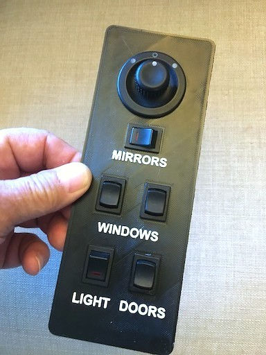
Shown above is what we started out to make. Getting from nowhere to here turned out to be quite an odyssey. But we usually enjoy such journeys, so we dove in.
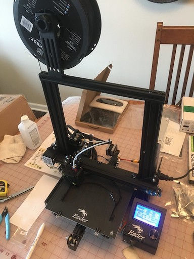
First we bought an Ender 3x 3D printer; that's ours above splayed out across our dining table/workbench. The Ender 3x is a great starter/hobbyist system costing just north of $200, and it comes complete with everything you need to print - except for the plastic material. You can print using at least two kinds of common plastic: ABS or PLA. Both have their distinct advantages.
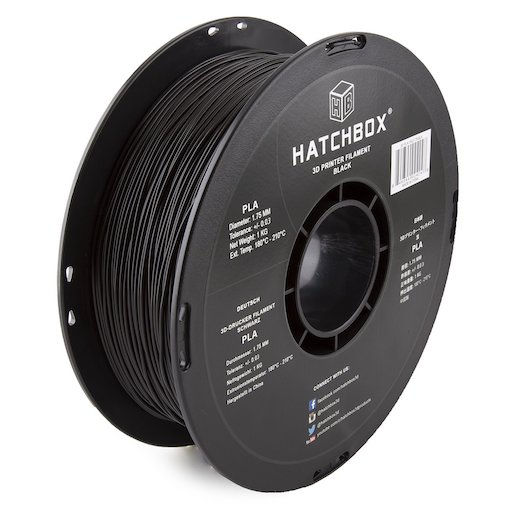
Our kids - who have been doing this 3D stuff for a while - recommended using PLA by Hatchbox, available on Amazon in a variety of colors. It is sold in 1.75mm gauge spooled onto a one kilogram roll. We chose black, of course.
Once our printer was assembled and working, the next challenge was coming up with a design for the replacement panel.

We used a software suite from AutoDesk calledFusion360 to design our panel, but there are other programs to choose from. Like many of those, Fusion360 is free to download for personal use and will run on either a macOS or Windows. After a bit of Googling and YouTube tutorial watching and general teeth gnashing, we managed to come up with what you see above: a prototype model of the new control panel.
(We would be remiss if we failed to point out that everything in the 3D printing world is done using the metric scale by default , so if you try 3D printing, a decent set of metric-capable calipers will quickly become your new best friend.)
Our replacement design had the same dimensions as the original control panel (H-W-D) replete with accurately sized and reasonably placed openings for the switches and mirror controls. We did take some editorial liberties with the labelling, however, using larger lettering raised 1mm above the top surface. We also changed MAP LT. to LIGHT, and we deleted the arrows for the WINDOWS and DOORS. Go figure.
Once our prototype design was complete, we needed to convert that into a format the 3D printer would understand. So we exported the panel from Fusion360 using a file format called STL (an abbreviation of "stereolithography"); it's commonly used in the 3D printing universe.
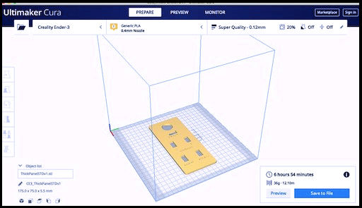
We were then able to import the STL version of the panel into another free computer tool named Ultimaker Cura. The latter, pictured above, is used to perform what's called slicing, literally cutting our Fusion360 design into multiple layers and converting it into a form called G-CODE. This G-CODE is the language a 3D printer understands.
In summary, the 3D workflow is:
Fusion360 design -> STL -> CURA -> G-CODE -> 3D printer
When the 3D printer reads the G-CODE, it can render a very accurate plastic copy of the design, doing so layer upon layer upon layer.
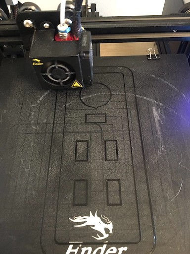
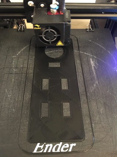
Above are a couple snapshots of the panel print in-progress. Our prototype panel was 4.5mm thick and was laid down in 30 separate layers of plastic; it took several hours to print. 3D Trivia: the plastic outline surrounding the panel is called a skirt; its purpose is to clean the nozzle head before starting to print the prototype itself.
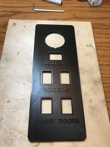
After a fair bit of trial and error, this is what came off the printer: a most-usable panel.
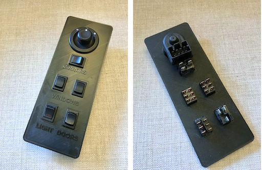
Here's the panel with the mirror control and switches installed. The fitment is great - no hot glue required.
The next problem was to figure out how to make the raised lettering more visible to the RV driver. Recall that the original panel was clear plastic screen printed on the bottom; that was for a reason: it was lit from below in order to be visible when the headlight switch was pulled. We had no illusions about trying to replicate that functionality. Besides, we know the panel controls by position and feel. Visible labels on the 3D design are there for someone not familiar with the coach.
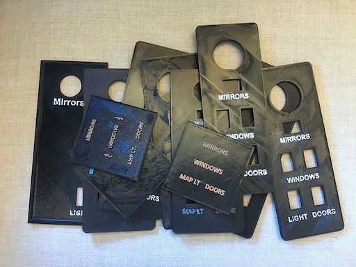
As shown above, we spent a lot of time testing different ways of coloring the raised lettering. Those tests included changing the PLA material color from black to a brighter hue at the precise moment the first raised lettering layer began to print. That approach turned out to be much too tedious and the results were disappointing, so we quickly abandoned a plastic color change in favor of painting.
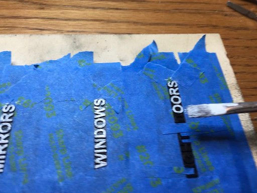
We tried several methods of painting the raised letters using white plastic model paint (Testors). The best method we found was to mask as much of the lettering as possible and dab the letters with a very lightly loaded paint brush.

It took three (3) thin coats to cover the letters properly, allowing ample time to dry between each coat. Note that this is absolutely a case where practice makes perfect and patience is a virtue, to throw out a couple proverbial phrases.
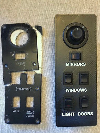
We hope you agree that we got the results we were after.
Conclusion
If you have the time and the patience, 3D printing is a viable means to produce some types of plastic replacement parts for your RV.
We are already planning some other replacement parts. It can only get easier, right?
BTW: we purposefully left the screw holes out of the replacement panel design; we're not sure if we will be using the original panel's mounting holes, as those contributed to its ultimate demise.
So we'll drill 'em when we get there.

Next Up
Installing the 3D Replacement Panel

Comments